 |
 |
|
|
(small).jpg) |
|
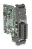
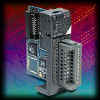
The CTRIO modules are our new High Speed I/O module for
DL05 / DL06, DL205, DL405, Terminator I/O, and Do-more control systems.
The modules have 8 counter / timer inputs (the H0-CTRIO has 4 inputs) that can be independently configured in a wide variety of ways. Here are some of the more popular configurations available:
The modules also have 4 outputs (H0-CTRIO has 2 outputs) that can be independently configured as follows:
Configuration of the CTRIO and CTRIO2 modules is done with Do-more Designer software (for Do-more PLCs), or the CTRIO Workbench utility for all other PLCs. Both use a graphical interface to setup the different operational modes. You'll simply use the configuration dialogs to define the inputs, outputs and tables the way you want. As you configure the various inputs and outputs, the CTRIO Workbench will dynamically change to show you what options have been chosen and what options remain. This means that you can't create a configuration that won't work, CTRIO Workbench won't let you define operational parameters that are incompatible. When you've completed the configuration for non-Do-more PLCs the CTRIO Workbench will write the settings to the module's FLASH memory. For Do-more PLCs the CTRIO configuration is stored as part of the System Configuration and downloaded to the CTRIO or CTRIO2 module each time the system is powered on. As part of it's normal operation, the CTRIO
and CTRIO2
modules can automatically scale the raw input values. There's a scaling
wizard to help you setup the scaling parameters and even a 'scaling
calculator' to let you test your scaling configuration before you commit
it to the module. Once the scaling has been setup, the CTRIO will present
both the raw and scaled values to the controlling CPU as often as needed. |
||||
(small).jpg)
.JPG)