
CTRIO
FAQ0001
<Deleted>
CTRIO
FAQ0002
16-Nov-2015
Q: What causes the CTRIO/CTRIO2 to sometimes get double counts or be
sensitive to noise?
A: If the CTRIO/CTRIO2 is counting double it is seeing double edges.
Use an oscilloscope to verify the signal. Spurious counting can be
caused by:
Things to consider:
CTRIO
FAQ0003
<Deleted>
CTRIO
FAQ0004
16-Nov-2015
Q: Can Pulse Profile parameters (e.g. accel/decel) be changed on the
fly from ladders?
A: No. However, here are some ideas to possibly solve this:
CTRIO
FAQ0005 (similar to DirectSOFT FAQ109; ERM FAQ0018)
08-Jul-2002
Q: While installing CTRIO Workbench various problems are encountered.
A: Although installation problems are uncommon the following errors
have been seen:
CTRIO
FAQ0006
21-May-2002
Q: Have CTRIO configured for Count Capture. When I get a pulse for
capture on Input D the count is captured properly. However when I get
a Reset on Input C not only is the current count cleared (as
expected), the captured count is also cleared!
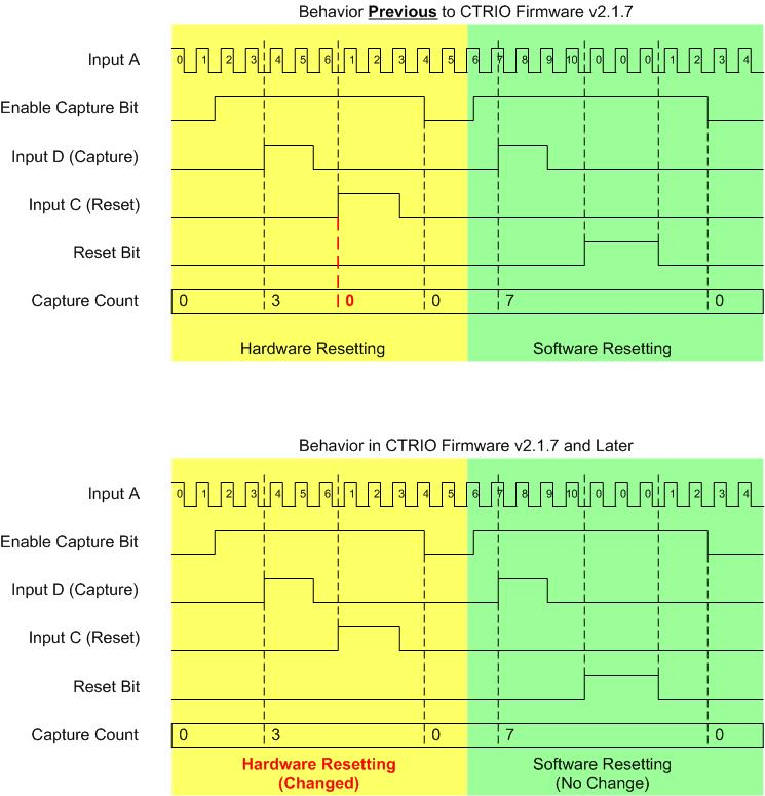
A: There are two ways in which a Reset can occur. (1) Hardware Reset
with Input C; (2) Software Reset with Reset Bit from PLC. Formerly the
Hardware Reset did indeed behave this way. It would clear both the
Current Count and the Captured Count. The Software Reset however, only
cleared the Current Count and left the Captured Count intact. However,
for consistency purposes (and some other reasons) we changed the
behavior of the Hardware Reset to be identical to that of the Software
Reset with regards to the clearing of the Capture Count. This behavior
was changed in H2-CTRIO firmware version v2.1.7. See below for Timing
diagrams.
CTRIO
FAQ0007
16-Nov-2015
Q: Are there examples of each of the CTRIO/CTRIO2 functions using
DL-PLC?
A: The manual describes them, and there are several example programs
and configuration files under the HAPTools\CTRIO and \HAPTools\CTRIOwb2
folders. However, it is highly recommended you use the Do-more PLC or at
least use the CTRIO IBox instructions in the DL-PLC. Using the
CTRIO/CTRIO2 using discrete DL instructions is very tedious and prone to
error.
CTRIO
FAQ0008 (see also DirectSOFT FAQ0224)
26-Sep-2017
Q: Encountering various problems when starting up CTRIO Workbench:
A: Here are some of the more common problems:
| CPU | Firmware | Hardware | Slot |
| DL05 | v4.60 | - | - |
| DL06 | v1.40 | - | Any |
| D2-240 | v3.22 | - | Not slot 0 |
| D2-250 | v1.56 | - | Not slot 0 |
| D2-250-1 | v3.5 | - | Not slot 0 |
| D2-260 | v1.2 | - | Not slot 0 |
| H2-WPLC | - | xK | Any |
| H2-EBC | v2.1.357 | - | Prior
Rev 9A --> Not slot 0 Rev 9A --> Any |
| H2-EBC100 | Any | - | Any |
| H2-PBC | Any | - | Prior
Rev 4A --> Not slot 0 Rev 4A --> Any |
| D4-450 | April
2000: H8 (CISC) v2.00 SH (RISC) v1.5000 May 2000: H8 (CISC) v2.00 SH (RISC) v2.500 |
- | Any |
| H4-EBC | v2.1.328 | v4F | Any |
| T1H-EBC | v1.0.444 | v2I | Any |
| T1H-EBC100 | Any | Any | Any |
| T1H-PBC | v1.1.10 | v2D | Any |
| T1K-DEVNETS | v1.80 | - | Any |
| T1K-MODBUS | v1.80 | - | Any |
CTRIO
FAQ0009
<Deleted>
CTRIO
FAQ0010
03-Jun-2002
Q: Variables in a CTRIO in PLC rack to Think&Do make sense in
Monitor I/O, but not when CTRIO is plugged into WinPLC.
A: We added the ability to display the Monitor I/O in several
different formats, including WinPLC format to CTRIO Workbench v2.0.
CTRIO
FAQ0011
03-Jun-2002
Q: CTRIO Workbench doesn't automatically enable link if you
double-click on it.
A: Added this feature to CTRIO Workbench v2.0.
CTRIO
FAQ0012 (see also WinPLC FAQ0036; EBC FAQ0079)
17-Nov-2015
Q: When trying to connect to CTRIO/CTRIO2 in WinPLC or EBC/EBC100
base with CTRIO Workbench, getting "Error reading base definition".
A: This is usually caused by the CTRIO Workbench not having enough
of the backplane bandwidth to complete a connection. Thus, depending on
what type of base the CTRIO/CTRIO2 is installed in:
If WinPLC: Try stopping the WinPLC's application from running; then try CTRIO Workbench again.
If EBC/EBC100: Try stopping the master that is currently polling, or disconnect from the master altogether; then try CTRIO Workbench again.
If none of this works, try reinstalling CTRIO Workbench. There have been instances where something on the PC has corrupted the installation and caused this very error message.
CTRIO
FAQ0013 (see also EBC FAQ0048; ERM FAQ0031; WinPLC FAQ0029; SDK
FAQ0013)
17-Nov-2015
Q: Is it possible to utilize the CTRIO System Functions everywhere
the CTRIO/CTRIO2 can be installed?
A: In firmware v2.x System Functions were added to the CTRIO
products (H0-, H2-, H4- and T1H-CTRIO) and are present in all CTRIO2
modules. These System Functions allow the writing (and reading) of
various internal registers of the CTRIO/CTRIO2. The following table
shows what scenarios that these System Functions can be used and how to
use them:
| System Functions | CTRIO/CTRIO2 Installation |
|||||||||
| Do-more Local Base | Do-more Ethernet I/O Base with EBC100 | DL PLC Local Base | DL PLC Local Expansion Base | DL PLC with ERM-EBC | WinPLC (Think&Do) Local Base | WinPLC (Think&Do) with ERM-EBC | Think&Do (Entivity) to EBC | Ethernet SDK to EBC | ||
| Mapped System Functions | Status of Inputs | YES (1) |
YES (1) |
YES (3) |
NO (5) | YES (3) |
YES (7) |
YES (7) | YES (7) |
YES (9) |
| Mode & Status of Outputs | YES (1) |
YES (1) |
YES (3) |
NO (5) | YES (3) |
YES (7) |
YES (7) |
YES (7) |
YES (9) |
|
| CTRIO/CTRIO2 Shared RAM System Functions | 0x01 - Read all registers | YES (2) |
YES (2) |
YES (4) |
NO (5) | NO (6) |
YES (8) |
YES (8) |
YES (8) |
YES (10) |
| 0x02 - Write all registers | YES (2) |
YES (2) |
YES (4) |
NO (5) | NO (6) |
YES (8) |
YES (8) |
YES (8) |
YES (10) | |
| 0x03 - Read one register | YES (2) |
YES (2) |
YES (4) | NO (5) | NO (6) |
YES (8) |
YES (8) |
YES (8) |
YES (10) | |
| 0x04 - Write one register | YES (2) |
YES (2) |
YES (4) | NO (5) | NO (6) |
YES (8) |
YES (8) |
YES (8) |
YES (10) | |
| 0x05 - Write reset value | YES (2) |
YES (2) |
YES (4) | NO (5) | NO (6) |
YES (8) |
YES (8) |
YES (8) |
YES (10) | |
(1) - Mapped to the
CTRIO/CTRIO2 device structure members
(2) - Use the CTREGWR & CTREGRD instructions (can
only read/write one register at a time)
(3) - Mapped to V-memory as configured in the
CTRIO/CTRIO2 using CTRIO Workbench
(4) - Use the CTRRGWR & CTRRGRD IBox instructions
(can only read/write one register at a time)
(5) - CTRIO/CTRIO2
will not work in local expansion bases
(6) - No way to tell the ERM/ERM100 to access the
Shared RAM of CTRIO/CTRIO2 in EBC/EBC100 base
(7) - Mapped to memory as configured in Think&Do
(8) - Use Shared RAM Operations for CTRIO/CTRIO2 in a
CALL block
(9) - Mapped as shown with NetEdit3 Show Base Contents
(10) - Use HEIWriteSharedRAM & HEIReadSharedRAM
routines
CTRIO
FAQ0014 (see also WinPLC FAQ0013, EBC FAQ0030)
17-Nov-2015
Q: What is the expected hit on the scan time for adding an
H2-CTRIO/CTRIO2 to WinPLC or EBC/EBC100 rack? When connected with
Entivity and adding more than one H2-CTRIO/CTRIO2 I get a timeout.
A: This is different for each product:
For WinPLC, there could be a detectable hit (however, small) simply because it has a comparatively slower processor (100MHz).
On the EBC/EBC100 itself, the addition of a CTRIO will probably not be noticeable at all simply because the EBC/EBC100 has only one thing to do . . . update its I/O.
On a Think&Do or Entivity application there will be about 7ms per CTRIO/CTRIO2 hit due to the number of tags that are created to handle the extra I/O scanning of the CTRIO/CTRIO2 from the PC. Thus, in the Connectivity Center of this software, under "Attributes" you must increase the "Timeout Value for Retries(ms)" value accordingly.
CTRIO
FAQ0015
17-Nov-2015
Q: If running velocity mode, can the number of pulses that have been
output be read?
A: Yes.
- If using a DL-PLC then use the CTRRGRD
"CTRIO Register Read" IBox and select the proper "Position" register.
- If using a Do-more PLC then use the CTREGRD "CTRIO Read Register"
instruction and select the proper "Position" register.
CTRIO
FAQ0016 (see also WinPLC FAQ0007)
17-Nov-2015
Q: Is there a way to change the preset values in multiple Preset
Tables from WinPLC to CTRIO on the fly?
A: Basically there are two choices to do this with CTRIO/CTRIO2:
CTRIO
FAQ0017
17-Nov-2015
Q: Can the CTRIO/CTRIO2 be made to count in both directions
(quadrature encoder) but only in a positive range (e.g. 0-499)?
A: Not easily. Here is how it could work:
In the above solution, the positive direction would work flawlessly, but the negative direction would be sensitive to the speed at which the encoder is turning along with the speed of the PLC scan. Also, depending on which direction is more critical in your application, you could just as easily make a Preset Table to handle the negative direction and the PLC program to handle the positive direction.
CTRIO
FAQ0018
17-Nov-2015
Q: What is the input impedance of the CTRIO/CTRIO2 input?
A: On the input of the CTRIO/CTRIO2 is a JFET (Junction Field Effect
Transistor) in a constant-current source arrangement. In this manner it
guarantees the input current will be between 5-15mA for the range of
9-30V. So, the input impedance varies based on this characteristic. So
at the high voltage extreme:
CTRIO FAQ0019
17-Nov-2015
Q: How does the Pulse Catch function operate? (The manual is a bit
unclear).
A: Below is an example timing diagram of the functionality of
Pulse Catch with notes at the end explaining. The settings used to
generate this diagram are not likely in the real world, but are given
here as only an example.
CTRIO Configuration for the
diagram:
- Input C = Pulse Catch
- Pulse In = Rising Edge
- Minimum Width In = 300µs
- Pulse Out Width = 1ms
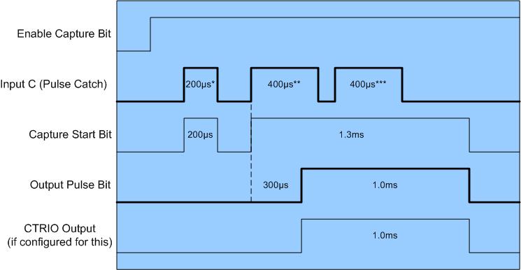
NOTES:
- The 1st thing to do is to SET the Enable Capture bit. This will cause the CTRIO/CTRIO2 to start looking for the pulse on Input C.
- The 1st pulse is ignored (200µs*) because it doesn't meet the 300µs minimum configured.
- The 2nd pulse is captured (400µs**) because it meets the 300µs minimum configured.
- The 3rd pulse is ignored (400µs***) because though it meets the 300µs minimum configured, it occurs during a capture.
- The Capture Start Bit comes ON as soon as an edge is detected and goes OFF if the pulse does not meet the 300µs minimum. However, it stays ON through the duration of a catch.
- The Output Pulse Bit comes ON as soon as the minimum 300µs minimum is met and stays ON for the Pulse Out Width of 1ms as configured.
- The CTRIO/CTRIO2 Output, if configured for this, will perfectly track the Output Pulse Bit.
Thus, the 2nd pulse is the one that is captured above, and reflected in the 1ms output. In a more practical application, the pulse width would probably be in the <25ms range (as above), but the Pulse Out Width would probably be much longer (e.g. >25ms) so that the PLC would be insured of "seeing" it.
CTRIO FAQ0020
17-Nov-2015
Q: Is it possible to reset the Preset Table's pointer back to the
1st entry in the Table without resetting the Count or disabling the
Output?
A: Yes. The "'round-about" way of doing this is to simply reload
the exact same unchanged Preset Table.
CTRIO FAQ0021
17-Nov-2015
Q: Will the CTRIO/CTRIO2 retain the current count upon power loss?
(i.e. Does it have retentive count capability?)
A: The CTRIO/CTRIO2 itself does not have this capability, however,
there is a way to accomplish this. If you are using the CTRIO/CTRIO2
in a DL-PLC then the CTRIO/CTRIO2 System Commands are utilized
along with the retentive V-memory of the host PLC. If you are
using the CTRIO/CTRIO2 in a Do-more PLC then this can be accomplished
by using some Do-more system features and the CTREGWR
instruction.
If you are using the CTRIO/CTRIO2 in a DL-PLC:

CTRIO FAQ0022
17-Nov-2015
Q: Trying to control a stepper motor drive, but sometimes it moves
in the wrong direction (e.g. staring up; homing).
A: Make sure that your stepper motor and stepper motor drive don't
have a minimum frequency. If they do, then make sure, of course, that
the CTRIO/CTRIO2 output frequencies are configured to put out at least
that minimum frequency requirement or else you can get erratic
performance (i.e. reversing direction) from your motor.
CTRIO FAQ0023
13-Aug-2002
Q: What is the resolution of the Edge Timer?
A: The maximum resolution is one microsecond (1µs).
CTRIO FAQ0024
17-Nov-2015
Q: The CTRIO/CTRIO2 stays in the booter (OK and ERR LEDs are
blinking) after attempting to upgrade its firmware; or gets "OS
loader failure" error.
A: This is normally a bandwidth problem (i.e. the firmware
telegrams aren't getting there in an efficient fashion. Here are some
things that will cause this if the firmware upgrade is attempted:
So, before attempting to upgrade, make sure that none of the above is true (e.g. PLC is in PGM mode; ERM (not EBC/EBC100) is unplugged from network to free up the EBC/EBC100; DirectSoft or Do-more Designer isn't connected at all; etc.). If your CTRIO/CTRIO2 is in the booter mode already (OK and ERR LEDs are blinking), just rerun the firmware upgrade with the above precautions.
CTRIO FAQ0025
06-Oct-2008
Q: When attempting to use the Import function for Freeform Pulse
Profile, get "Error on line 1: ..." no matter what I do.
A: This is a bug exclusive to CTRIO Workbench v2.1.11 (all earlier
versions work). This can be fixed by upgrading to:
CTRIO Workbench v2.1.12 (or later)
To download the latest CTRIO Workbench:
(1) Goto www.hosteng.com.
(2) In left column, click Hardware --> CTRIO.
(3) Scroll down to CTRIO Workbench v2.1.12 (or later) link.
CTRIO FAQ0026 (see also EBC FAQ0082; PBC
FAQ0013; WinPLC FAQ0037)
17-Nov-2015
Q: Why are the I/O Map values not saved if using CTRIO Workbench to
talk to a CTRIO in an EBC/EBC100, WinPLC, or PBC base?
A: If the CTRIO/CTRIO2 is in any of these bases, the values
entered in the CTRIO Workbench I/O Map do not
determine the CTRIO's I/O address mapping. Something other than the
CTRIO/CTRIO2 itself is determining this mapping (see chart below).
Thus the I/O Map, in these cases, is merely a documentation function.
If you enter values in this map, they will not be saved in the CTRIO/CTRIO2's .CWB file that you might create. Thus, to remember the values, you will have to use the Report button at the bottom and then either Print a hard copy, or Save it to a .TXT file.
| BASE CONTROLLER | MASTER OF THE BASE CONTROLLER | I/O MAPPING DETERMINED or SHOWN BY: |
| DL05 | N/A | CTRIO Workench (I/O Map) |
| DL06 | ||
| DL205 | ||
| DL405 | ||
| Do-more (H2-DM1, H2-DM1E, T1H-DM1, T1H-DM1E) |
Do-more
Designer CTRIO Structure Members |
|
|
H2-EBC, H2-EBC100, H4-EBC |
PC (Ethernet SDK) | H2-EBC, H2-EBC100, H4-EBC (NetEdit --> Show Base Contents) |
| PC (KepDIRECT EBC) | ||
| PC (Think&Do or Entivity) | ||
| H2-ERM, H2-ERM100, H4-ERM |
ERM Workbench (Configure ERM/ERM100) | |
| Do-more
Ethernet I/O |
Do-more Designer CTRIO Structure Members | |
| H2-EBC100 only | 3rd-party (Modbus TCP) | H2-EBC100 (NetEdit --> Show Base Contents) |
| H0-ECOM100, H2-ECOM100, H4-ECOM100 (Modbus TCP) | ||
| Do-more
(Modbus TCP) |
||
| H2-WPLC (Think&Do or Entivity) | <N/A> | H2-WPLC (Think&Do or Entivity) |
| H2-WPLC (WinCE) | H2-WPLC (3rd-party application) | |
| H2-PBC | 3rd-party (Profibus Master) | 3rd-party (Profibus configurator) |
| T1H-EBC or T1H-EBC100 | PC (Ethernet SDK) | T1H-EBC or T1H-EBC100 (NetEdit --> Show Base Contents) |
| PC (KepDIRECT EBC) | ||
| PC (Think&Do or Entivity) | ||
|
H2-ERM, H2-ERM100, H4-ERM |
ERM Workbench (Configure ERM/ERM100) | |
| Do-more
Ethernet I/O (H2-DM1E, T1H-DM1E) |
Do-more Designer CTRIO Structure Members | |
| T1H-EBC100 only | 3rd-party (Modbus TCP) | T1H-EBC100 (NetEdit --> Show Base Contents) |
| H0-ECOM100, H2-ECOM100, H4-ECOM100 (Modbus TCP) | ||
| Do-more (Modbus TCP) |
NOTE: To use the table, note what is controlling the base where the CTRIO/CTRIO2 is plugged into. Then note what is controlling the base controller itself. In the last column is the device or software that either determines the I/O mapping, or at least shows it to you.
CTRIO FAQ0027
17-Nov-2015
Q: Is it possible to write a value to the current count in the
CTRIO/CTRIO2?
A: Yes.
CTRIO FAQ0028
17-Nov-2015
Q: It appears that the CTRIO/CTRIO2 sometimes misses the Z-pulse
from my encoder.
A: If this appears to happen (usually at higher frequencies) then
you should upgrade the CTRIO to at least v2.0 or use a CTRIO2. There
was a small window of time in the older CTRIO (v1.0) where it was
possible for this to occur. The CTRIO firmware v2.0.1 and greater
fixes this.
CTRIO FAQ0029
17-Nov-2015
Q: How many counters can the CTRIO/CTRIO2 support?
A: The H2-CTRIO/CTRIO2 and H4-CTRIO can have 2 quadrature or 4
regular counters configured. The H0-CTRIO/CTRIO2 can have 1 quadrature
and 2 regular counters configured.
CTRIO FAQ0030
18-Nov-2015
Q: Using Process Commands, the Command Complete bit never gets
set. Everything in Monitor I/O works, however.
A: Consider:
CTRIO FAQ0031
18-Nov-2015
Q: I need to read both the speed/velocity of my encoder input as
well as the position (raw count). Is this possible?
A: Both the Scaled Units and the Raw Value are output from the
CTRIO/CTRIO2 to the DL-PLC in the I/O Mapping dialog:

CTRIO FAQ0032
18-Nov-2015
Q: I need to control a CTRIO/CTRIO2 output based on both a
speed/velocity input reading from my encoder as well as the position
(raw count). Is this possible?
A: Even though Scaled Units and Raw Value are output from the
CTRIO/CTRIO2 to the DL-PLC in the I/O Mapping and the CTRIO/CTRIO2
structure members in the Do-more PLC, you cannot configure a single
CTRIO/CTRIO2 output to respond based on both the speed/velocity
(Scaled Units) value and the position (Raw Value). You could, however,
hook the encoder to 2 channels of the CTRIO/CTRIO2 and use 2 outputs;
1 to respond to the speed/velocity (Scaled Units) value and the other
to respond to the position (Raw Value).
CTRIO FAQ0033
18-Nov-2015
Q: Will the H2-CTRIO/CTRIO2 work with the F2-DEVNETS-1?
A: No, the H2-CTRIO/CTRIO2 will not work with the F2-DEVNETS-1
(nor the earlier F2-DEVNETS) nor are there any plans to make these
work together.
CTRIO FAQ0034 (see also ERM FAQ0019; EBC
FAQ0029)
18-Nov-2015
Q: Will the CTRIO/CTRIO2 work in the local expansion bases of
DL205 or DL405 line?
A: No. Do not install the H4-CTRIO nor the H2-CTRIO/CTRIO2 in
local expansion. It will however work in the ERM/EBC configuration. So
you can expand the I/O using the ERM/EBC instead.
CTRIO FAQ0035
18-Nov-2015
Q: How many quadrature encoders can I connect to a CTRIO/CTRIO2?
A: The H2-CTRIO/CTRIO2 and H4-CTRIO can support 2 quadrature
encoders each. The H0-CTRIO/CTRIO2 can support only 1.
CTRIO FAQ0036
18-Nov-2015
Q: Using Temposonic quadrature absolute encoder, and occasionally
the count in the CTRIO/CTRIO2 module jumps by 65,536 counts.
A: The Temposonic quadrature encoders actually artificially
generate pulse trains based on the absolute position of their magnets.
The faster versions are of high enough resolution that when they are
at rest the electronic pulse generator inside is actually jittering.
This causes direction changes for the CTRIO/CTRIO2 that are much too
fast for it to handle (i.e. out of spec for the speed of the inputs);
in fact, the direction changes are taking place faster than a real
encoder with real mechanical motion could possibly generate. Thus it
is not recommended that these style of encoders be used with the
CTRIO/CTRIO2 unless you make sure that the resolution is large enough
(i.e. not as sensitive) so as not to artificially generate these
direction changes too quickly.
CTRIO FAQ0037
18-Nov-2015
Q: How is the Rate calculation performed by the CTRIO/CTRIO2.
A: Here are some real-life applications to help you understand
how these settings work:
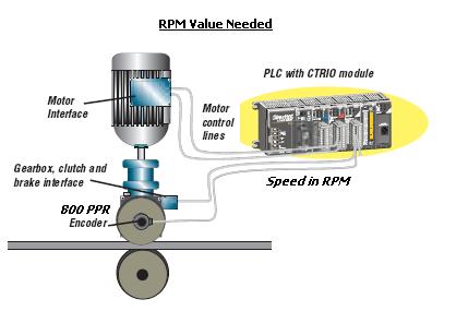
EXAMPLE #1 (RPM Value)
Let's say we want the CTRIO/CTRIO2 to give us the speed of a motor in RPMs (Revolutions Per Minute) instead of just counts. Attached to this motor we have an encoder that yields 800 PPR (Pulses Per Revolution). This encoder is connected to the CTRIO/CTRIO2's Inputs and the CTRIO/CTRIO2 Input has been configured as a Counter.
Thus the givens for this example are:
- Rate value needs to be in RPMs.
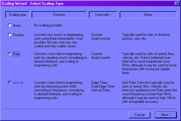
- Encoder is 800 PPR.We now pull up the Scaling Wizard by pressing the Ruler (
) button. This gives the following dialog:
Pick Rate and press the <Next> button. This yields the following dialog:
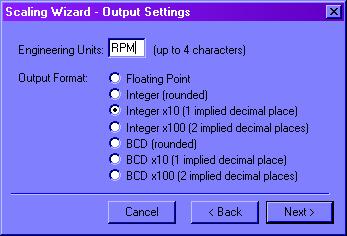
Engineering Units: This is strictly 4 characters that can have any meaning we want. CTRIO/CTRIO2 doesn't care.
Output Format: This is how we want the scaling value reported to us. In this example, Integer x10 is picked just because we want a tenth of an RPM accuracy in the value reported. This means, for example, if we get a value back from the CTRIO/CTRIO2 such as 2124, this has 1 implied decimal place, which means the value is actually 212.4. We now press the <Next> button and get the following dialog:
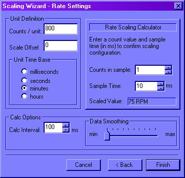
Since we want our value to be in RPMs (Revolutions Per Minute), then we must set the Unit Time Base as minutes. Now, remember the encoder we are using yields 800 pulses in 1 revolution. Thus if it made 1 revolution in 1 minute, that would yield 800 pulses in 1 minute's time. So if the CTRIO/CTRIO2 Inputs see 800 pulses in the timespan of 1 minute, this would be 1 RPM. Thus, we must make the Counts / unit equal to 800 (800 pulses per minute = 1 RPM). Basically, we are done with the scaling and there is nothing else to configure. The Calc Options do not affect the scaling calculation being performed but are explained in CTRIO FAQ0070 and CTRIO FAQ0081.
Notice in this dialog, however, there is a tool called the Rate Scaling Calculator that can be used to verify our settings. Let's use it and see if it gives what we think it should:
Counts in sample: This is a number of counts we are going to consider. To make it easy, let's just say the CTRIO/CTRIO2 receives 800 pulses from the encoder, and thus counts to 800. So we enter 800.
Sample Time: This is the timespan in which the 800 pulses were received. Since we already know if the CTRIO/CTRIO2 gets 800 pulses in the timespan of 1 minute would equal 1 RPM, then we want to make the Sample Time equal to 1 minute. But the Sample Time is in ms (milliseconds). Thus, to enter 1 minute; this would be 60 seconds, or 60,000 milliseconds. So we enter 60000.
Scaled Value: Here is the answer. It will display 10 RPM. This is not 10 RPM, but rather 1.0 RPM because, in the Output Settings above we picked an implied decimal place. This proves that if the CTRIO/CTRIO2 gets 800 pulses in the timespan of 60,000 ms, that this would equal 1 RPM.RATE SCALE FORMULA FOR RPM EXAMPLE
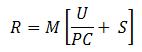
The formula the CTRIO/CTRIO2 uses to calculate the Rate Scaling is:
Or simplified as:
Where:
R = Result (This value is the Rate Scaling value output by the CTRIO/CTRIO2 to the PLC)
M = Multiplier (This value depends on the Output Format selected in the Scaling Wizard - Output Settings dialog).
U = Units in seconds (This value depends on the Unit Time Base selected in the Scaling Wizard - Rate Settings dialog).
C = Counts per unit (This value is the Counts / unit entered in the Scaling Wizard - Rate Settings dialog).
S = Scale offset (This value is the Scale Offset entered in the Scaling Wizard - Rate Settings dialog).
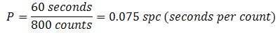
P = Pulse interval in seconds (This value is the Input to the CTRIO/CTRIO2 that is being scaled. It is the time in seconds divided by the number of counts received):
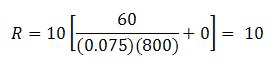
Using this formula with the RPM example above:
- M = 10 because Output Format = Integer x 10 (1 implied decimal place).
- U = 60 because Unit Time Base = minutes (1 minute = 60 seconds).
- C = 800 because Counts / unit = 800.
- S = 0 because Scale Offset = 0 (this is the case most of the time).
Since we are going to scale a particular count as received in a particular amount of time, let's use something we already know. We know in our example that if the CTRIO/CTRIO2 sees 800 pulses in 1 minute, that would be 1 RPM. Thus:
- P = 0.075 because:
Plugging the values in:
This is the same answer we received when we plugged the values into the Rate Scaling Calculator.
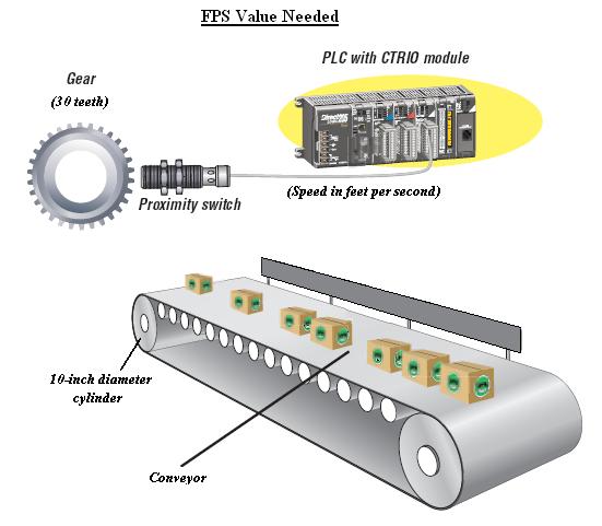
EXAMPLE #2 (FPS Value)
RPM scaling is the easiest example. Let's try something more complicated. Let's say we have a conveyor belt running and we want the value obtained from the CTRIO/CTRIO2 to be FPS (Feet Per Second). A proximity switch is connected to the CTRIO/CTRIO2 Input that detects the teeth on a gear. The gear has 30 teeth on it, and is coupled directly to a cylinder being driven by a motor to move the conveyor belt. The diameter of the cylinder is 10 inches.
Thus the givens for this example are:
- Rate value needs to be in FPSs.
- Proximity switch & Gear provide 30 PPR.
- Cylinder driving the belt is 10 inches in diameter.The CTRIO/CTRIO2 can only see the pulses generated from the proximity switch. Since we want the value the CTRIO/CTRIO2 gives us to be in FPS (Feet Per Second), we're going to have to figure out how much the cylinder must turn (and thus the gear with teeth detected by the proximity switch) to make the belt move 1 foot (12 inches). To figure this out, we must know the cylinder's circumference. If the cylinder's diameter is 10 inches, then:
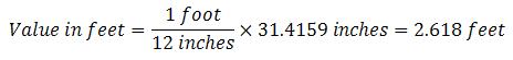
This means when the cylinder turns 1 full turn, it has moved the belt 31.4159 inches. This 1 turn of the cylinder would also turn the gear 1 full turn, and thus generate 30 pulses on the proximity switch. Thus 30 pulses = 31.4159 inches of belt movement. But we are interested in feet, not inches. Since there are 12 inches in 1 foot:
This means when the cylinder turns 1 full turn, it has moved the belt 2.618 feet. Again, this 1 turn of the cylinder would also turn the gear 1 full turn, and thus generate 30 pulses on the proximity switch. Thus 30 pulses = 2.618 feet of belt movement. Now in order to configure the CTRIO/CTRIO2 to give us the right value, we need to know how many pulses the CTRIO/CTRIO2 Input will see if the belt only travels 1 foot because we are interested in FPS (Feet Per Second). Thus:
Of course, the CTRIO/CTRIO2 cannot see a fraction of a pulse, but the calculation for the Rate can certainly use a fraction. Thus we now know that when the cylinder has turned 1 foot, and thus turned the gear, the proximity switch will have generated at least 11 pulses. Thus, if the CTRIO/CTRIO2 sees 11 pulses, it knows the belt has traveled at nearly 1 foot. Realizing this, we can set the values.
We now pull up the Scaling Wizard by pressing the Ruler (
Pick Rate and press the <Next> button. This yields the following dialog:
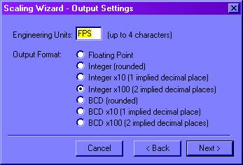
Engineering Units: This is strictly 4 characters that can have any meaning we want. CTRIO/CTRIO2 doesn't care.
Output Format: This is how we want the scaling value reported to us. In this example, Integer x100 is picked just because we want a hundredth of a FPS accuracy in the value reported. This means, for example, if we get a value back from the CTRIO/CTRIO2 such as 2124, this has 2 implied decimal places, which means the value is actually 21.24. We now press the <Next> button and get the following dialog:
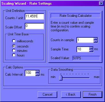
Since we want our value to be in FPS (Feet Per Second), then we must set the Unit Time Base as seconds. Now, remember the gear/proximity switch we are using yields 30 pulses in 1 revolution, but only yields 11.4591 pulses when the belt has traveled 1 foot. So if the CTRIO/CTRIO2 Inputs see 11 pulses in the timespan of 1 second, this would be almost (but not quite) 1 FPS. Thus, we must make the Counts / unit equal to 11.4591 (11.4591 pulses per second = 1 FPS). Basically, we are done with the scaling configuration. The Calc Options do not affect the scaling calculation being performed but are explained in CTRIO FAQ0070 and CTRIO FAQ0081.
Notice in this dialog, however, there is a tool called the Rate Scaling Calculator that can be used to verify our settings. Let's use it and see if it gives what we think it should:
Counts in sample: This is a number we are going to consider. To make it easy, let's just say the CTRIO/CTRIO2 receives 11 pulses from the proximity swtich, and thus counts to 11. So we enter 11.
Sample Time: This is the timespan in which the 11 pulses were received. Since we already know if the CTRIO gets 11 pulses in the timespan of 1 second this would be almost 1 FPS, then we want to make the Sample Time equal to 1 second. But notice the Sample Time is in ms (milliseconds). Thus, to enter 1 second; that would be 1000 milliseconds. So we enter 1000.
Scaled Value: Here is the answer. It will display 96 FPS. This is not 96 FPS, but rather 0.96 FPS (almost 1 FPS) because, in the Output Settings above we picked 2 implied decimal places. This proves that if the CTRIO/CTRIO2 gets 11 pulses in the timespan of 1000 ms, that this would equal nearly 1 FPS as we expect. Remember the exact number of pulses for traveling 1 foot is technically 11.4591, but the CTRIO/CTRIO2 can't see fractional pulses, of course. But by increasing the Counts in sample to 12, you can see that the answer would now indicate slightly over 1 FPS, e.g. 1.05 FPS as we expect.RATE SCALE FORMULA FOR FPS EXAMPLE
Using this formula with the FPS example above:
- M = 100 because Output Format = Integer x 100 (2 implied decimal places).
- U = 1 because Unit Time Base = seconds.
- C = 11.4591 because Counts / unit = 11.4591.
- S = 0 because Scale Offset = 0 (this is the case most of the time).
Since we are going to scale a particular count as received in a particular amount of time, let's use something we already know. We know in our example that if the CTRIO/CTRIO2 could see fractional pulses and it saw 11.4591 pulses in 1 second, that would be exactly 1 FPS. But since it can only see integer values for pulses, let's just use 11 pulses. As we saw above, this should give us a value less that 1 FPS. (The Rate Scaling Calculator gave us 96). Thus:
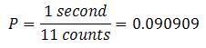
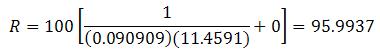
- P = 0.090909 because:
Plugging the values in:
Rounded up, this is the same answer we received when we plugged the values into the Rate Scaling Calculator.
CTRIO FAQ0038
23-Nov-2015
Q: Using Data Smoothing for a Rate calculation in H2-CTRIO, the
initial value is way off, but after several samples it starts
working correctly.
A: This was a bug in the CTRIO firmware. This behavior is
corrected in v2.0.1 firmware and in the H2-CTRIO2 module.
CTRIO FAQ0039 (see also EBC FAQ0038; PBC
FAQ0006)
27-Aug-2002
Q: In order to use the T1H-CTRIO or H4-CTRIO, what are the
requirements as far as configuration software, hardware and
firmware?
A: Here are the requirements:
CTRIO FAQ0040
08-Oct-2002
Q: When my CTRIO outputs are tied to Preset Tables, I cannot
disable them. Why?
A: CTRIO outputs have two names:
CTRIO FAQ0041
08-Oct-2002
Q: What is the minimum firmware version of the DL250-1 necessary
to work with the H2-CTRIO?
A: All DL250-1 PLCs work with the H2-CTRIO. However, if you have
the older DL250, then it must have firmware v1.56 or later.
CTRIO FAQ0042
23-Nov-2015
Q: When CTRIO/CTRIO2 is powered up, the ERR light comes on.
A: This ERR light indicates a serious and fatal error in the
CTRIO/CTRIO2 has occurred. Check:
CTRIO FAQ0043 (see also EBC FAQ0043; PBC
FAQ0008)
23-Nov-2015
Q: How many T1H-CTRIO/CTRIO2s can be installed in one base?
A: For T1H-EBC/EBC100, 13. For T1H-PBC, 2. The limit is data
budget.
CTRIO FAQ0044
23-Nov-2015
Q: Using a Preset Table I cannot get RESET COUNT at 1250 and RESET
COUNT at -1250 to work.
A: This problem actually stems from a misunderstanding as to how
the CTRIO/CTRIO2's Preset Tables function. Your table:
RESET COUNT at 1250
RESET COUNT at -1250
When the CTRIO/CTRIO2 sees a RESET COUNT instruction it zero's the count as expected, but it also resets the pointer back to the beginning of the table; which means that once the count is reset after reaching the value of 1250, it is goes back and starts looking for 1250 to happen again.
The function you are trying to get to work
is more properly called a programmable limit switch (PLS). PLS
functionality has been added to the CTRIO2. So to do this, instead of
using Preset Tables, configure a PLS in the CTRIO2.
CTRIO FAQ0045 (see also DirectSOFT FAQ0132; DL
Plus FAQ0010; DNLoader FAQ0011; DS Data FAQ0102; EBC FAQ0083; ECOM
FAQ0084; EDRV FAQ0084; ERM FAQ0058; EZ Ethernet FAQ0010; General
FAQ0004; HA-TADP FAQ0008; Lookout Direct FAQ0015; NetEdit FAQ0037; PBC
FAQ0014; PSCM FAQ0003; SDK FAQ0022; SERIO FAQ0004; WinPLC FAQ0038)
31-Dec-2009
Q: What is the export classification of your products (e.g. ECCN)
A: None of our products have an ECCN. Automation Direct sells our
products and they export EAR99 NLR (No License Required). ECCN
is Export Controlled Classification Number and none of our
products are controlled.
CTRIO FAQ0046 (see also EBC FAQ0047; ECOM
FAQ0036; EDRV FAQ0009; ERM FAQ0030; EZ Ethernet FAQ0018; PBC FAQ0009;
PSCM FAQ0001; WinPLC FAQ0018; NetEdit FAQ0014; MB-GATEWAY FAQ0003;
Do-more FAQ0038)
23-Nov-2015
Q: What software tool do I use to upgrade/downgrade my Host
Engineering hardware?
A: Refer to the following:
| Host Hardware | Part Number | Firmware/Booter Upgrade Tool |
|
CTRIO CTRIO2 |
H0-CTRIO H4-CTRIO H0-CTRIO2 |
CTRIO
Workbench |
|
H2-CTRIO
T1H-CTRIO H2-CTRIO2 T1H-CTRIO2 |
CTRIO
Workbench or Do-more Designer |
|
| EBC EBC100 |
H2-EBC H4-EBC T1H-EBC T1H-EBC100 H2-EBC100 |
NetEdit3 |
| ECOM ECOM100 |
H0-ECOM H2-ECOM H4-ECOM H0-ECOM100 H2-ECOM100 |
|
| EDRV EDRV100 |
GS-EDRV GS-EDRV100 |
|
| ERM ERM100 |
H2-ERM H4-ERM H2-ERM100 |
NetEdit3
or ERM Workbench |
| EZ Ethernet | EZ
Ethernet EZ EtherPLUS |
EZ Touch |
| MB-GATEWAY | MB-GATEWAY | NetEdit3 |
| PBC | H2-PBC | |
| PSCM |
H0-PSCM
H2-PSCM
|
|
| WinPLC | WinPLC | WinPLC Workbench |
NOTE: All the firmware for the above products can be downloaded using NetEdit3's File --> Live Update... The firmware files are stored in c:\HAPTools\Images folder.
CTRIO FAQ0047
23-Nov-2015
Q: What do the values in the Workspace register mean in the various
CTRIO IBoxes?
A: The Workspace register is used internally by the CTRIO IBoxes.
Consequently, one should never write to this register. However,
knowing the meaning of the various possible values can aid in
troubleshooting the IBox if something goes wrong.
Generally the Workspace bits are defined as follows:
- Bit0 (i.e. Workspace = 1): Waiting for leading edge
trigger of the IBox (power flow is OFF).
- Bit1 (i.e. Workspace = 2): Waiting for token (after
leading edge is seen).
- Bit2 (i.e. Workspace = 4): Waiting for CTRIO/CTRIO2's
Command Complete bit to go OFF
- Bit3 (i.e. Workspace = 8): Waiting for CTRIO/CTRIO2's
Command Complete to come ON
Here are possible interpretations of these
values:
- Workspace = 1: This means the IBox has seen that the
input leg to the IBox is OFF and is now waiting for the input leg to
come ON (thus providing the leading edge to get things going).
- Workspace = 2: This means the IBox has seen the leading
edge trigger and is ready to execute, however, it doesn't have the
internal token yet. In other words, there is some other CTRIO IBox that
is currently executing for the same CTRIO/CTRIO2 module, it it has to
wait for that one to finish and release the token.
- Workspace = 4: This means the IBox has seen the leading
edge trigger and now has the token. It is now only waiting for the
possibility that the CTRIO/CTRIO2's Command Complete bit has not yet
turned OFF from a previous operation. This is just a quick check to make
sure the CTRIO/CTRIO2 module is ready for a new Command.
- Workspace = 8: This means the IBox has seen the leading
edge trigger, has the token, the Command Complete bit is OFF, and has
executed his code giving the CTRIO/CTRIO2 a new Command to do and is now
waiting for the CTRIO/CTRIO2 module to tell him he has completed the
task.
Thus if you watch the Workspace register you will see it cycle through values 0, 1, 2, 4, 8 and back to 0 pretty fast.
If the IBox, for example, seems to not work and you look at the Workspace register and it is frozen at a value of 8, this usually means you have executed that particular IBox, say, in a Stage, and have terminated that Stage before the IBox gave you a Success or Error bit.
CTRIO FAQ0048
15-Feb-2008
Q: How do I change direction on the Pulse Outputs (i.e. direction
of the motor)?
A: Direction is changed depending on the Pulse Profile you have
loaded to control the Pulse Output.
| COMMAND CODE | TABLE | DIRECTION CHANGE | EXAMPLE MAPPING (1) |
| 0x10 - Load Table | Trapezoid | Direction bit | C204 |
| S-Curve | Direction bit | C204 | |
| Symmetrical S-Curve | Direction bit | C204 | |
| Dynamic Positioning | Parameter3 & Current Position (2) | V2020-V2021 (decimal) |
|
| Dynamic Velocity | Sign of Parameter3 (3) | V2020-V2021 (signed decimal) |
|
| Home Search | Direction bit | C204 | |
| Free Form | Direction bit | C204 | |
| 0x20 - Velocity Mode | (4) | Direction bit | C204 |
| 0x21 - Run to Limit Mode | (4) | Direction bit | C204 |
| 0x22 - Run to Position Mode | (4) | Direction bit | C204 |
NOTES:
(1) - The example mapping is
based on PLC - Mapped Addresses (4 ranges) with:
Starting V address for word inputs: V2000-V2017
Starting V address for bit inputs: V40600.0-V40605.15 (C0-C137)
Starting V address for word outputs: V2020
Starting V address for bit outputs: V40606.0-V40613.15 (C140-C277)
(2) - The CTRIO determines the direction by taking
the difference between Parameter3 minus Current Position. If the
result is positive, the Pulse Outputs will go one way; if negative,
the other.
(3) - Parameter3 is a signed decimal double-word.
If it is negative, Pulse Outputs will go in one direction; if
positive, the other.
(4) - No tables are associated with these direct
commands.
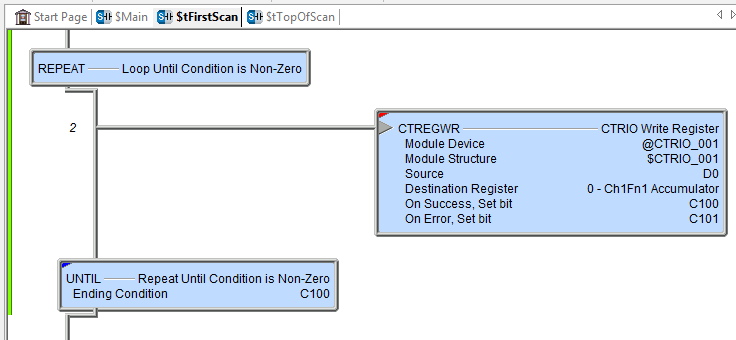
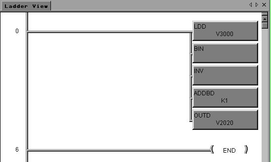
For NOTE (3) above, to load a negative value (32-bit 2's compliment; decimal) into Parameter3 (e.g. V2020-V2021) starting with a BCD number in V3000-V3001 you would do the following logic; if, however, the value in V3000-3001 is already in binary format then you would, of course, leave out the BIN box:
CTRIO FAQ0049
01-Nov-2002
Q: Can the H2-CTRIO interrupt the PLC when it reaches a certain
count like the CTRINT module?
A: No. The H2-CTRIO does not have the ability to interrupt the
CPU like the CTRINT. The reason is the DL205 backplane does not have
an interrupt line for each slot. The slot adjacent to the CPU (Slot 0)
has 4 of its address lines converted to interrupt lines that are only
useable by the CTRINT.
CTRIO FAQ0050
02-Dec-2002
Q: Is the CTRIO configuration stored in battery-backed-up RAM?
A: No. The configuration for the CTRIO is stored in NVRAM
(Non-volatile RAM) and therefore will not be lost on power failure or
battery failure.
CTRIO FAQ0051 (see also DirectSOFT FAQ0163; ERM
FAQ0032)
10-Dec-2002
Q: Will DirectSOFT work on Win95 32-bit OS?
A: We have seen this work on a few and not work on others. If it
doesn't work we do not know of anything that can be done to make it
work. However CTRIO Workbench and ERM Workbench will not even install
if the InstallShield engine (used to install DirectSOFT) recognizes
that the PC is Win95.
CTRIO FAQ0052
19-Dec-2002
Q: Is there a minimum load required for the CTRIO outputs?
A: No. The CTRIO output is a FET (Field Effect Transistor) which
is normally 50m Ω(ohms). Leakage for this device is typically at 150μ
amps at temperature extremes. Thus if the load is so small as to
require only 150μ amps, then it could inadvertently turn on.
CTRIO FAQ0053
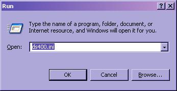
10-Feb-2003
Q: Installed CTRIO Workbench v2.0 but no options to launch it
show up in DSLaunch.
A: By installing CTRIO Workbench v2.0, changes are made to the
DS400.INI file. However because you are using an older version of
DirectSOFT these menu items cannot be displayed in DSLaunch. In order
for these launch items to show up on the DSLaunch menu, CTRIO
Workbench v2.0 requires at least DirectSOFT v4.0 Build 18.
CTRIO FAQ0054
27-Mar-2014
Q: Need to know more about how to configure and control the
CTRIO2 from the DL-PLC and Do-more program.
A: Below are 3 sets of flow charts (in PDF format) that will help
you control the CTRIO2 from ladder logic either in a DL-PLC without
IBoxes, a DL-PLC with IBoxes or a Do-more PLC. They can also be used
with the CTRIO module if consideration is given to the limited
functionality of the CTRIO versus the CTRIO2.
CTRIO FAQ0055 (see also EBC FAQ0049)
10-Mar-2003
Q: Are there any slot restrictions for the CTRIO if installed
in an EBC?
A: The following restrictions apply:
CTRIO FAQ0056
13-Mar-2003
Q: While testing Run-to-Position function using Monitor I/O;
it seems it doesn't function properly when I enter certain values
for the next position.
A: This was a bug in CTRIO Workbench v2.0. The problem was that in
Monitor I/O the position value in the CTRIO was internally using an
Integer instead of a Floating Point value. To fix, upgrade to CTRIO
Workbench v2.1.
CTRIO FAQ0057
20-Jul-2004
Q: In the Automation Direct catalog (pg. 4-68) it is stated
that the CTRIO under certain conditions can output a pulse of up to
50 KHz; but Monitor I/O will not allow me to input a frequency
higher than 25 KHz.
A: This was an original intention of the CTRIO, but it did not end
up that way. The catalog is incorrect as the CTRIO stands now. The
upper limit of the Pulse Output is indeed 25 KHz like Monitor I/O
limits you to.
CTRIO FAQ0058
22-Apr-2010
Q: Will a TTL encoder work with the CTRIO?
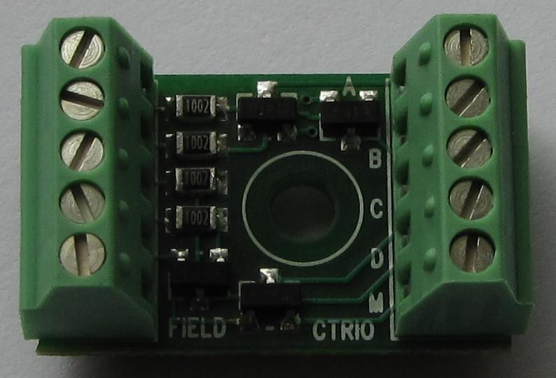
A: Not directly; you will have to build a circuit to step up the
voltage into the CTRIO's specified range or you can order a board
built by Host Engineering:
Part Number:
CTRIO-TTLANNEX
Price: $25 each
How to order: Send e-mail to
purchasing@hosteng.com with the following information:
- Your company name & address.
- Contact name, phone number & e-mail.
- Quantity
- Purchase Order #
NOTE: At this time we do not accept credit
cards as a payment method. We will invoice you for the total cost.
- Shipping preferences (e.g. Use your UPS
account? Bill you?)
- Shipping address & phone number (if
different than above)
Size: Approximately 1" length x 1/2" wide x 3/8" thick, with mounting screw hole.
Picture:
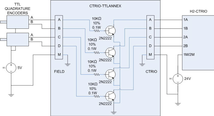
Wiring diagram:
CTRIO FAQ0059
09-Nov-2004
Q: What is the maximum length between edges that the CTRIO's Edge
Timer can measure?
A: The CTRIO's Edge Timer can measure a maximum of 268,435,455µs
between edges. (i.e. 268.4 seconds or about 4 ½ minutes).
CTRIO FAQ0060
18-Nov-2004
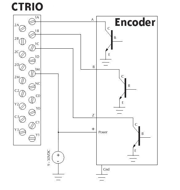
Q: How can I wire an open-collector quadrature encoder to the
CTRIO?
A: You can use the following diagram for the H2-CTRIO for all
CTRIOs. Just pay attention to the signal names on the CTRIO connector:
CTRIO FAQ0061
06-Aug-2004
Q: What causes the Output Stalled error bit to come on?
A: This bit means the Pulse Output train was interrupted because
the CTRIO was too busy doing other things. Some things to try:
CTRIO FAQ0062 (see also EBC FAQ0054; NetEdit
FAQ0015)
02-Feb-2005
Q: Using an EBC100 and Modbus TCP protocol, how can I figure out
where the CTRIO parameters are mapped into the Modbus addresses?
A: The easiest way to do this is to use NetEdit3 and CTRIO
Workbench in combination. Follow these steps:
Here you can see that NetEdit3 has provided the Modbus addressing for you. Next you need only to see how these work in the CTRIO.
After manually entering these numbers from NetEdit3 into CTRIO Workbench's I/O mapping screen you can now see all the parameters and their appropriate Modbus TCP addressing.
CTRIO FAQ0063
15-Feb-2005
Q: Can I change the default folder for storing the CTRIO Workbench
configuration files (.CWB)?
A: Yes. CTRIO Workbench uses the default projects folder as
defined in the DS400.INI (or DS300.INI) file. When CTRIO Workbench
starts up it looks for the DS300.INI file first and if it finds it, it
will use the default projects folder as defined there. If it does not
find the DS300.INI file, it will look for the DS400.INI file and use
the default projects folder as defined there. If it cannot find the
DS400.INI file then it will fault with: "Critical Error - ERROR 1004 -
Invalid INI File" and will close when you press the <OK> button.
To change the default folder:
Now when you use the <Write File> button the default folder will be the one you entered.
CTRIO FAQ0064
16-Feb-2005
Q: Using the "BCD (rounded)" selection for Position Scaling; the
Position Scaling Calculator depicts a different behavior than what
the CTRIO actually does.
A: Yes, this is a bug in the Position Scaling Calculator in
versions of CTRIO Workbench of v2.1.9 or less. The incorrect behavior
is in the Position Scaling Calculator itself. The CTRIO is actually
functioning correctly in that it rounds the scaled value up like you
would think (and like the function's name says). However, the Position
Scaling Calculator does not round up; instead it is truncating the
fraction.
CTRIO FAQ0065
08-Mar-2005
Q: How many Presets can be added to each Preset Table?
A: 255.
CTRIO FAQ0066
08-Mar-2005
Q: How many Presets Tables can the CTRIO have?
A: 255.
CTRIO FAQ0067
08-Mar-2005
Q: Can the duty cycle of the pulse output be changed if using
Dynamic Velocity or Dynamic Positioning?
A: No. The duty cycle of the pulse output can, however, be
changed using the System Commands "0x20 - Velocity Mode" and "0x22 -
Run-to-Position Mode."
CTRIO FAQ0068
21-Sep-2005
Q: Can the accel/decel rates of the Dynamic Velocity Pulse Profile
be increased to greater than 50,000? (i.e. instantaneous)
A: No. The highest rate is 50,000. If instant change from one
frequency to another is desired you will have to use the Free Form
Pulse Profile. This Pulse Profile has no accel/decel parameters and so
you can output a number of pulses at one frequency and then go
instantly to a different number of pulses at a different frequency. Of
course the downside is that you no longer have the "dynamic" feature
of Dynamic Velocity Pulse Profile.
CTRIO FAQ0069 (see also EBC FAQ0066)
26-Jul-2005
Q: When using H2-CTRIO in H2-EBC100, the Output Active bit for the
CTRIO doesn't come on, however, it works in an H2-EBC.
A: This is a bug caused by the firmware of the H2-EBC100. The
DWORD outputs were not getting written to the CTRIO properly. It is
fixed in:
H2-EBC100 firmware v4.0.457 or higher.
CTRIO FAQ0070
14-Nov-2005
Q: When using Data Smoothing, what do each of the notches mean from
"min" to "max"?
A: From "min" to "max" each notch represents an increasing number
of samples that are averaged together to get a smoothing affect. The
exact number of samples that are averaged respectively from "min" to
"max" positions are:
For Rate Data Smoothing (10 slider positions): 1, 2, 3, 5, 7, 10, 13, 17, 21, 25
For Interval Data Smoothing (12 slider positions): 1, 2, 3, 5, 7, 10, 13, 17, 21, 25, 30, 36
CTRIO FAQ0071
10-Nov-2005
Q: When using Interval Rate Scaling, if Data Smoothing is adjusted
to anything other than Minimum, zero (0) is given in the Scaled
Value answer.
A: This is a bug in CTRIOs with firmware that was accidentally
introduced in v2.0.1 and up. Firmware v1.x actually worked! However,
we have fixed this problem in the latest CTRIO firmware (v2.1.15).
CTRIO FAQ0072 (see also EBC FAQ0072; ERM
FAQ0047; SDK FAQ0015)
09-Jan-2006
Q: In my H2-ERM/H2-EBC (or H2-EBC100) configuration, the H2-CTRIO
word output (WO) and double-word output (DWO) mapping is different
than where CTRIO Workbench indicates they should be.
A: This is caused by an I/O mapping problem in the H2-EBC and
H2-EBC100 that is fixed in EBC firmware v2.1.441 and later. It has to
do with the H2-CTRIO "I/O type." The H2-CTRIO is now reported as a
Type 7 module instead of a Type 5 module. This new reclassification of
the H2-CTRIO as a Type 7 allows the EBC to manage the order in which
things get mapped.
The symptom shows up as a mapping discrepancy in the order in which the CTRIO puts the DWOs and the WOs VS where the ERM Workbench maps them in PLC memory.
For example, for comparison see the chart below:
| H2-CTRIO Mapping Component | H2-CTRIO mapping in H2-EBC (H2-EBC100) with firmware less than v2.1.441 | H2-CTRIO Mapping in H2-EBC (H2-EBC100) with firmware v2.1.441 or later |
| 96 Discrete Input (DI) | X340-477 (V40416-40423) | X340-447 (V40416-40423) |
| 96 Discrete Output (DO) | Y320-457 (V40515-40522) | Y320-457 (V40515-40522) |
| 12 Word Output (WO) | V2100-2113 | V2110-2123 |
| 8 Double Word Input (DWI) | V2000-2017 | V2000-2017 |
| 4 Double Word Output (DWO) | V2114-2123 | V2100-2107 |
NOTE: If you update the EBC firmware to fix this problem, make sure that you are at least using CTRIO Workbench v2.1.10 to configure the H2-CTRIO.
CTRIO FAQ0073
03-Jan-2006
Q: Can the Reset Value as configured on the Config I/O page of
CTRIO Workbench be changed on the fly from ladders?
A: No, not that one. Basically there are two Reset Values:
CTRIO FAQ0074
31-Jan-2006
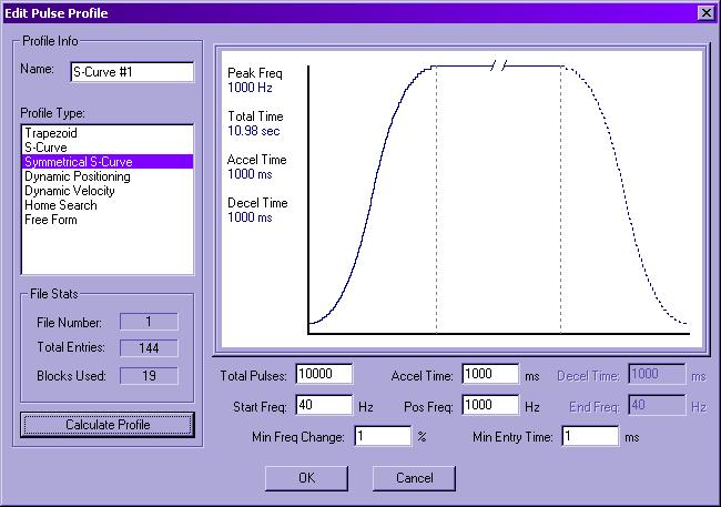
Q: In the S-Curve (& Symmetrical S-Curve) Pulse Profiles, what
do the Min Freq Change and Min Entry Time parameters do?
A: These parameter define the resolution of the S-Curve itself.
First of all, the CTRIO is not designed to be a sophisticated motion
control device. When you use CTRIO Workbench to configure an S-Curve
Pulse Profile, Workbench calculates entries for a table that defines
the curve. It is this table that is downloaded into the CTRIO itself.
In other words, the CTRIO itself does not do complex math "on the fly"
to come up with this curve; that would take too much valuable CTRIO
scantime. Instead, the CTRIO is just blindly outputting values from
this predefined table. With that understanding:
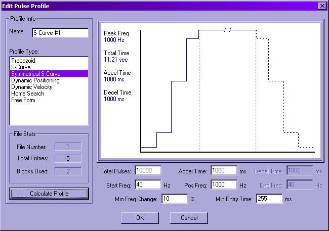
Min Freq Change: This is a percentage (between 1-10%) that changes the vertical frequency resolution of the output curve. In other word, it is the Y-axis of the graphical representation that you see in CTRIO Workbench. If you change this value and press the <Calculate Profile> button you will notice the vertical resolution of the graph changes. With 1% the CTRIO can use more frequencies and so it is smoother; at 10% the CTRIO will use less frequencies and so it become very course.
Min Entry Time: This is a time (between 1-255ms) that changes the horizontal time resolution of the output curve. In other words, it is the X-axis of the graphical representation that you see in CTRIO Workbench. If you change this value and press the <Calculate Profile> button you will notice the horizontal resolution of the graph changes. With 1ms the CTRIO can use smaller steps and so it is smoother; at 255ms the CTRIO will use less time increments and so it becomes very course.
Thus, with these 2 parameters you control the smoothness of the CTRIO output curve. If you make both parameters very small, the S-Curve will look very smooth, but you also create a bigger table and thus take up more configuration space in the CTRIO:
If you make both parameters very large, the S-Curve will look very course, but you also create a smaller table and thus take up very little configuration space in the CTRIO.
CTRIO FAQ0075
08-Feb-2006
Q: Will the CTRIO support differential encoder outputs?
A: No. The CTRIO inputs are single-ended in that the M connection
is common to all 4 inputs (A, B, C, D). Tying 2 differential encoder
outputs together is not a good idea so we'd be limited to 1 input at
the most (e.g. A and M). Also because of the sink/source capabilities
of the CTRIO inputs, a positive or a negative signal above 9V
threshold would be treated as an ON. So even using a single
differential signal greater than 9V each side of ground (M), the CTRIO
would count both states as ON and therefore count at twice the
expected rate. If distance and electrical noise are the reason for
using the differential encoder, twisted pair wiring is usually good
enough because the CTRIO inputs stay OFF at up to 2 mA and 2V.
CTRIO FAQ0076
13-Feb-2006
Q: Using quadrature counter at 1X, how does the CTRIO increment
counts after a reset? Does it synchronize to the rising edge of
Input A?
A: After a reset, the CTRIO count defaults to the DOWN direction.
Thus if the CTRIO is to count pulses in the UP direction after the
reset, then, depending on the configuration, it may need as much as 4
edges to reestablish the UP direction. However, if the CTRIO is to
count pulses in the DOWN direction, it will continue without having to
reestablish a direction.
For the COUNTING-UP scenario, the rules are:
For 1X quadrature counting: After the reset CTRIO is in the DOWN direction. It takes 4 edges to reestablish the UP direction. On the 4th edge CTRIO will increment the count and then from this point onward it will increment the count on the rising edge of Input A
For 2X quadrature counting: After the reset CTRIO is in the DOWN direction. It takes 2 edges to reestablish the UP direction. On the 2nd edge CTRIO will increment the count and then from here it will increment the count when Input A and Input B are in opposite states or after 2 more edges (which ever comes first). Then from this point onward it will increment the count when Input A and Input B are in opposite states.
For 4X quadrature counting: After the reset CTRIO is in the DOWN direction. It only takes 1 edge to reestablish the UP direction. So CTRIO counts all edges all the time.
These COUNTING-UP rules are displayed in the following tables:
Count gets Reset while Input A = 0 and Input B = 0:
Input A Input B Count (1X) Count (2X) Count (4X) 1 0 0 0 1 1 1 0 1 2 0 1 0 1 3 0 0 1 2 4 1 0 2 3 5 1 1 2 3 6 0 1 2 4 7 0 0 2 4 8 1 0 3 5 9 Count gets Reset while Input A = 1 and Input B = 0:
Input A Input B Count (1X) Count (2X) Count (4X) 1 1 0 0 1 0 1 0 1 2 0 0 0 1 3 1 0 1 2 4 1 1 1 2 5 0 1 1 3 6 0 0 1 3 7 1 0 2 4 8 1 1 2 4 9 Count gets Reset while Input A = 1 and Input B = 1:
Input A Input B Count (1X) Count (2X) Count (4X) 0 1 0 0 1 0 0 0 1 2 1 0 0 1 3 1 1 1 2 4 0 1 1 3 5 0 0 1 3 6 1 0 2 4 7 1 1 2 4 8 0 1 2 5 9 Count gets Reset while Input A = 0 and Input B = 1:
Input A Input B Count (1X) Count (2X) Count (4X) 0 0 0 0 1 1 0 0 1 2 1 1 0 1 3 0 1 1 2 4 0 0 1 2 5 1 0 2 3 6 1 1 2 3 7 0 1 2 4 8 0 0 2 4 9
For the COUNTING-DOWN scenario, the rules are:
For 1X quadrature counting: After the reset CTRIO is in the DOWN direction therefore it will continue to count down on the falling edge of Input A.
For 2X quadrature counting: After the reset CTRIO is in the DOWN direction therefore it will continue to count down when Input A and Input B are in the same state.
For 4X quadrature counting: After the reset CTRIO is in the DOWN direction therefore it will continue to count down on all edges all the time.
These COUNTING-DOWN rules are displayed in the following tables:
Count gets Reset while Input A = 0 and Input B = 0:
Input A Input B Count (1X) Count (2X) Count (4X) 0 1 0 0 -1 1 1 0 -1 -2 1 0 0 -1 -3 0 0 -1 -2 -4 0 1 -1 -2 -5 1 1 -1 -3 -6 1 0 -1 -3 -7 0 0 -2 -4 -8 0 1 -2 -4 -9 Count gets Reset while Input A = 0 and Input B = 1:
Input A Input B Count (1X) Count (2X) Count (4X) 1 1 0 -1 -1 1 0 0 -1 -2 0 0 -1 -2 -3 0 1 -1 -2 -4 1 1 -1 -3 -5 1 0 -1 -3 -6 0 0 -2 -4 -7 0 1 -2 -4 -8 1 1 -2 -5 -9 Count gets Reset while Input A = 1 and Input B = 1:
Input A Input B Count (1X) Count (2X) Count (4X) 1 0 0 0 -1 0 0 -1 -1 -2 0 1 -1 -1 -3 1 1 -1 -2 -4 1 0 -1 -2 -5 0 0 -2 -3 -6 0 1 -2 -3 -7 1 1 -2 -4 -8 1 0 -2 -4 -9 Count gets Reset while Input A = 1 and Input B = 0:
Input A Input B Count (1X) Count (2X) Count (4X) 0 0 -1 -1 -1 0 1 -1 -1 -2 1 1 -1 -2 -3 1 0 -1 -2 -4 0 0 -2 -3 -5 0 1 -2 -3 -6 1 1 -2 -4 -7 1 0 -2 -4 -8 0 0 -3 -5 -9
CTRIO FAQ0077
13-Feb-2006
Q: Does the Scan Time of the CTRIO (as indicated in CTRIO
Workbench) affect the response time of the Pulse Output to Presets
in the Preset Tables?
A: Yes. There are 3 levels of processing in the CTRIO; (1)
hardware dependant; (2) interrupt dependant and (3) scan time
dependant. In the case of Presets in the Preset Tables that change the
state of the Pulse Outputs, this is handled in the (3) scan time
dependant processing. Thus, the maximum time from reaching a Preset
count to a change in the Pulse Output as configured in a Preset Table
is the Scan Time of the CTRIO. For this to be any different the CTRIO
would have to have much faster hardware, which would be more
expensive. Thus for an example:
Count coming into the CTRIO rising-edge
counter at a rate of 25 KHz and we have a Preset Table with an entry of
SET at 12 and a CTRIO Scan Time of 600 µs.
- At 25 KHz, that is a rising edge every
1 / 25000 = 0.00004 seconds (or 40 µs)
- The count of 12 will take 12 x 40 µs =
480 µs
- If this event occurred immediately
after the CTRIO had already updated its Pulse Outputs, then it could be
about 600 µs before the Pulse Output was updated. Thus an event that
should've happened in 480 µs ended up taking 480 + 600 = 1.08 ms. This
would tend to give you a similar response for all Preset Values that are
faster than the Scan Time of the CTRIO.
CTRIO FAQ0078
13-Feb-2006
Q: Does the CTRIO have a "follower" mode (i.e. produce a Pulse
Output at the same velocity as an encoder input)?
A: No, there is no intrinsic follower mode for the CTRIO. The only
way to make the CTRIO Pulse Output follow the Rate of a CTRIO counter
input is:
This should work well in most applications simply because the delay between a change of Rate on the CTRIO Input to the change of Velocity on the CTRIO Pulse Output will, at the most, be about 2 PLC scantimes (i.e. in the millisecond range).
CTRIO FAQ0079
27-Feb-2007
Q: What is the difference between Edge-Triggering and
Level-Triggering?
A: Here are the differences:
EDGE TRIGGERING: The inputs are sampled by the CTRIO hardware every 16 MHz clock cycle. If the edge exceeds 2V and 2mA, then an edge is reported to the CTRIO firmware as a trigger interrupt. Thus the CTRIO hardware is totally in control of the triggering.
LEVEL TRIGGERING: The inputs are sampled by the CTRIO hardware every 16 MHz clock cycle. If the edge exceeds 2V and 2mA, then a change of state is reported to the CTRIO firmware. As the CTRIO firmware scans and notices there has been a change of state from 0 to 1 of one of its inputs, then it "knows" there was a trigger. Thus the triggering is based not on just an edge detection by the hardware, but also is somewhat delayed by the scantime of the CTRIO.
Therefore, if edge triggering is falsely being triggered by an excessively noisy signal, oftentimes changing to level triggering will filter these false triggers out. However, nothing is a good substitute for a clean signal on the inputs in the first place.
CTRIO FAQ0080
09-Mar-2007
Q: Can the configuration of the CTRIO be printed out using CTRIO
Workbench?
A: No, but the configuration can be saved in a .CWB file. The only
thing that can be printed out is the I/O map.
CTRIO FAQ0081
15-Feb-2010
Q: What does the Calc Interval have to do with Rate
and Interval Scaling?
A: Calc Interval is just so you can tell the CTRIO how
many times you want the CTRIO to calculate the Rate or Interval
scaling. In other words, if you need a more accurate measurement and
are monitoring the value closely (i.e. high-speed), then calculating
this value more frequently would be needed. But is would be useless to
calculate it faster than the scantime of your PLC, since the PLC can
only look at the value once per scan anyway. If, however, the value is
not that high-speed and not needed by the process to be very accurate,
then calculating this value less frequently would be better.
CTRIO FAQ0082 (see also PBC FAQ0016)
22-Nov-2010
Q: Cannot get CTRIO Workbench's Monitor I/O function to work with
the PBC.
A: Unfortunately, it is not possible to have this
functionality for the CTRIO in the PBC. To comply with specification,
CTRIO Workbench cannot suspend the PBC's writing/reading the CTRIO's
I/O in order to perform the function, thus it is not supported.
CTRIO FAQ0083
07-Mar-2011
Q: How fast is the CTRIO-TTLANNEX board?
A: The transistors themselves are actually rated at 300 MHz, but
due to other design restraints we do not recommend you go over 10
MHz. However, if you are using them with the current CTRIO
module itself, the CTRIO input can only go to 100 KHz.
CTRIO FAQ0084
07-Apr-2011
Q: Edge detection on the Run to Limit function (CTRRTLM IB-1011)
doesn't work properly.
A: The problem here is the documentation. The Run-to-Limit function
in the CTRIO does NOT use an edge
detection but rather a level detection.
The CTRIO manual (pgs. 6-42 thru 6-43), the DirectSOFT Help file (help
for CTRRTLM IB-1011 IBox) and our very own CTRIO
Flow Charts.PDF document all had this wrong. Thus, since it is a
level detection on the Limit Input, the "Both Edges" detection
setting is invalid and the "Rising Edge" is actually a "High
Level" and the "Falling Edge" is actually a "Low
Level". The idea, for example, in the real world was if the
machine was already at the limit switch (Limit Input) then it is not
necessary to move the machine at all.
The following chart show the correct values for Parameter2:
00 Channel 1 Input C
high level limit
10 Channel 1 Input C low level limit
01 Channel 1 Input D high level limit
11 Channel 1 Input D low level limit
02 Channel 2 Input C high level limit
12 Channel 2 Input C low level limit
03 Channel 2 Input D high level limit
13 Channel 2 Input D low level limit
The CTRIO manual will be corrected in the
next release.
The DirectSOFT Help file will be corrected in the next release.
The CTRIO Flow Charts.PDF
document has been corrected already.
CTRIO
FAQ0085
24-Aug-2011
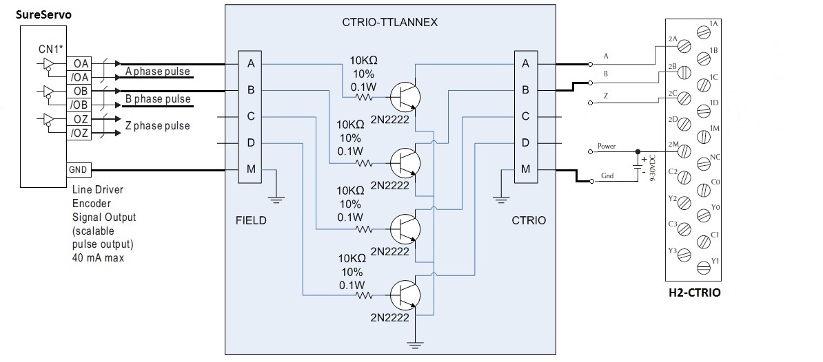
Q: Is it possible to connect the TTL-level differential encoder
outputs of the SureServo to the CTRIO?
A: Yes. But it is necessary to use the CTRIO-TTLANNEX board to step
up the voltage levels for the CTRIO inputs. Also since the SureServo
encoder outputs on connector CN1 are differential (0A, /OA, OB, /OB, OZ,
/OZ) and the CTRIO inputs are single-ended, the /OA, /OB and /OZ signals
cannot be used. Instead only the OA, OB and OZ with reference to any GND
terminal on CN1 are needed.
CTRIO FAQ0086 (see also
Do-more FAQ0028)
14-Mar-2013
Q: Must CTRIO Workbench be used to
configure CTRIO and CTRIO2s in Do-more?
A: No, CTRIO Workbench cannot be used with Do-more. Instead,
the configuration of CTRIO/CTRIO2 modules is done in Do-more Designer
software in the PLC --> System
Configuration --> Module Configuration. The CTRIO/CTRIO2
configuration is no longer stored in the module itself, but
rather the Do-more CPU (DM1/DM1E).
Also, in Do-more the CTRIO/CTRIO2 parameters are not mapped into
V-memory as was the case in DL-PLCs. Instead the various
CTRIO/CTRIO2 parameters are mapped to Do-more Structured memory as
Structured members (e.g. CTRIO_000_C1F1.AtResetValue
is CTRIO zero Channel 1 Function 1's "at reset" parameter bit). See
table below for members that can exist. Not all members exist for
every CTRIO/CTRIO2 configuration. See Do-more Designer Help file for
specific details for any given CTRIO/CTRIO2 configuration and useage
(i.e. ladder instructions):
| STRUCTURE e.g. CTRIO_000_... |
FUNCTION (2) | GENERAL
DESCRIPTION (see Do-more Help file for specifics) |
||||||
| INPUT SCHEMAS | OUTPUT SCHEMAS | GLOBAL | ||||||
| MEMBER (1) | Counter | Pulse Catch | Edge Timer | Discrete | Raw | Pulse | ||
| CxFx.AtResetValue | RO | BIT - Indicates when count is at the Reset value | ||||||
| CxFx.CaptureComplete | RO | BIT - Indicates the 2nd edge has been detected and a timer value is available | ||||||
| CxFx.CapturedStart | RO | RO | BIT - Indicates an edge has been detected (Pulse Catch) or 1st edge has been detected (Edge Timer) | |||||
| CxFx.CountCaptured | RO | BIT - Indicates an edge has been detected and a count value is available | ||||||
| CxFx.EnableCapture | R/W | R/W | R/W | BIT - ON enables Pulse Catch or Edge Timer function | ||||
| CxFx.fReg1 | RO | RO | REAL - Various meanings based on configuration (e.g. floating-point scaled count for Counter) | |||||
| CxFx.fReg2 | RO | RO | REAL - Various meanings based on configuration | |||||
| CxFx.iReg1 | RO | RO | DWORD - Various meanings based on configuration (e.g. raw count for Counter) | |||||
| CxFx.iReg2 | RO | RO | DWORD - Various meanings based on configuration (e.g. raw count if Counter value is scaled) | |||||
| CxFx.Output | RO | BIT - Output pulse of Pulse Catch function | ||||||
| CxFx.Reset | R/W | BIT - ON resets Counter value to Reset value | ||||||
| CxFx.Timeout | RO | BIT - Indicates edge not seen in allotted time | ||||||
| Outx.AtPosition | RO | BIT - Indicates output pulse has reached commanded position | ||||||
| Outx.AtVelocity | RO | BIT - Indicates output frequency has reached commanded frequency | ||||||
| Outx.Direction | RO | BIT - Indicates cloclwise (OFF) or counter-clockwise (ON) direction for Pulse Output | ||||||
| Outx.EnableOutput | R/W | RO | BIT - ON enables output for Discrete function use with Discrete Tables | |||||
| Outx.GotoPosition | R/W | BIT - Must be turned ON to move to target position; CTRIO/CTRIO2 will reset OFF when moving | ||||||
| Outx.Output | R/W | BIT - Turn ON to turn Raw output ON | ||||||
| Outx.OutputActive | RO | RO | BIT - Indicates with Output is ON or generating pulses | |||||
| Outx.OutputEnabled | RO | RO | BIT - Indicates if Output has been enabled | |||||
| Outx.OutputPosition (3) | RO | DWORD - Current position of pulse output | ||||||
| Outx.OutputStalled | RO | BIT - Indicates if Pulse output has stalled (not able to keep up) | ||||||
| Outx.OutputSuspended | RO | BIT - Indicates if Pulse output has been suspended | ||||||
| Outx.OutputVelocity (3) | RO | DWORD - Current frequency of the Pulse output | ||||||
| Outx.TableComplete | RO | BIT - Indicates when a Discrete Table has reached its last entry | ||||||
| .ErrorCode | RO | WORD - Last error code | ||||||
| .Mode | RO | WORD - 1=PROGRAM; 2=RUN | ||||||
| .ScanTime | RO | WORD - Scantime in microseconds | ||||||
| .MaxScanTime | RO | WORD - Maximum scantime in microseconds | ||||||
| .InputState | RO | WORD - Lower byte indicates input's states (see details in Help file) | ||||||
| .OutputState | RO | WORD - Output configuration (see deatils in Help file) | ||||||
| .ChxA | RO | BIT - Indicates state of Channel x Input A | ||||||
| .ChxB | RO | BIT - Indicates state of Channel x Input B | ||||||
| .ChxC | RO | BIT - Indicates state of Channel x Input C | ||||||
| .ChxD | RO | BIT - Indicates state of Channel x Input D | ||||||
| .OutxType | RO | BIT - Indicates if Output x is configured for Pulse output | ||||||
| .OutxDiscOn | RO | BIT - Indicates Output x logic is ON (if Output is enabled then physical output will also be ON) | ||||||
| .OutxDiscEnabled | RO | BIT - Indicates if Output x is configured for Discrete output | ||||||
| .OutxPulseActive | RO | BIT - Indicates Output x is generating pulses | ||||||